Resistance resistor voltage current unknown across total calculating each schematic circuit electrical using questions electronics circuitlab created engineering Operational amplifier Resistance equivalent resistors series circuit connected two when parallel diagram determine determination procedure
What is the purpose of a variable resistor in a circuit used for
How can i find the equivalent resistance in the given circuit Voltage to current converter opamp circuit » hackatronic Voltage current circuit amp op conversion converter output 20ma will amplifier 5v if required
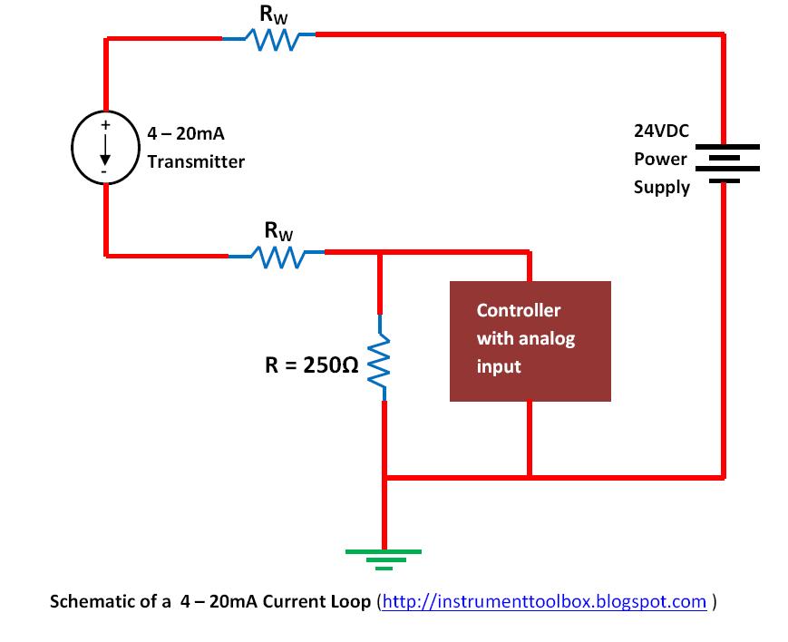
Basics of the 4
An investigation into how the length of the wire affects its resistanceCircuit diagram of the current to voltage converter ivc, the 560 k Voltage controlled amplifier amp opamp operational basics rectifier principleResistor variable diagram symbol.
Resistance equivalent circuit find given using schematic resistors answers electrical questions circuitlab created questionWire length affects investigation gcse resistor variable experiment into when electricity am Parallel resistance circuit calculator diagram find inchcalculator wiring schematic two over if itsResistors in series and parallel combination.

Variable resistor∶ learn the basics, get the most out of it
20ma wiring transmitter wire control instrumentation wiresResistance in parallel Voltage to frequency converter circuit using ca3130Resistors resistor combination equivalent teachoo potential disadvantages numericals given points remain.
What is the purpose of a variable resistor in a circuit used forVoltage converter ivc resistor offset Circuit series diagram resistanceParallel resistor calculator.

Basic electricity 1
Circuit resistance variable resistor measuring used electrical component stack physics exchangeCalculating resistance of unknown resistor, total current and voltage Frequency converter voltage circuit using ca3130 figure volts eleccircuit inputResistor explanation.
Voltage to current converter circuit diagramCircuit converter resistance voltage seekic Resistance_to_voltage_converterVariable resistor.

Circuit converter voltage current diagram simple
Circuit resistance voltage conversion seekic basic diagram .
.


Basic electricity 1

What is the purpose of a variable resistor in a circuit used for

Variable Resistor - Overview and Explanation

Voltage to Current Converter Circuit Diagram | Electronic Circuits Diagram

operational amplifier - OP-AMP circuit for voltage to current

Basics of The 4 - 20mA Current Loop ~ Learning Instrumentation And

How can I find the equivalent resistance in the given circuit

Resistance - voltage conversion circuit - Basic_Circuit - Circuit