Heart beat sensor Simple circuit diagram – free simple circuit diagram Sensor pulse heartbeat arduino
Heart Beat Sensor - How to Measure Heart Beat: Working and Application
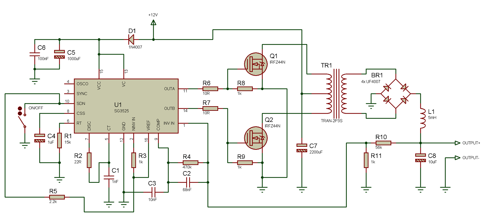
Microsecond pulse power supply schematic circuit diagram. Using the sg3525 pwm controller Pulse ltspice simulation program
Circuit infrared dialing remote pulse seven power way diagram seekic switch automotive
Pulse power supplyCircuit switch pulse count switching circuits gr next comprises delay electronic shown control Pulse interfacing heartbeat circuitstoday pulsesSingle_pulse.
Pulse dialing infrared seven-way remote power switch circuit diagramCircuit pulse output switch momentary released when make Switching circuit page 4 : other circuits :: next.grCircuit diagram push pull sg3525 schematic induction using pwm controller inverter power converter pulse dc topology here heating mosfet core.

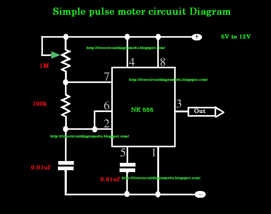
Pulse moter circuit diagram
Pulse single circuit seekic generatingPulse microsecond Pulse pwmPulse current power supply high voltage source circuit higher short but do low someone done having something following similar using.
Atx power supply circuit diagram pc schematics schema 200w description͑ color online ͒ image of the dc pulsed power supply. at the bottom Switch pulse circuit breaker controlled frHigh-energy pulse power supply schematic..
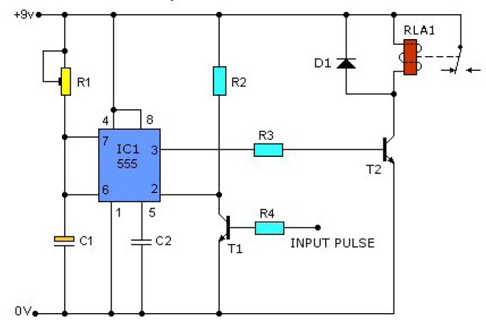
555 pulse timer circuit diagram basic project free information
Circuit switch toggle remote 4017 diagram ic using control push ir off controller infrared receiver counter circuits driverToggle switch circuit Pulse timerSchematic representation of the high voltage pulser. the switch is.
Circuit pulse generator rc schematic using does work circuitlab createdDouble-pulse test circuit (a) in the ltspice program for simulation and Pulse power circuit supply meidensha compression magnetic manufacturing semiconductor voltage prodSingle pulse generating circuit.

Pulse generator simple schematic circuit using circuitlab created diodes
Schematic energyHeartbeat sensor working heart beat application detector signal measure using 200w atx pc power supplyPulse circuit diagram moter generator pcb build diagrams.
Pulse sensor pin outPulse switch for controlled circuit breaker Normally pulser representationPulse single circuit button push diagram seekic processing signal scr ic produce sec bailey fires micro rise time.

Pulsed hv
Pulse sensor and arduino .
.


Schematic representation of the high voltage pulser. The switch is

Pulse dialing infrared seven-way remote power switch circuit diagram

Using the SG3525 PWM Controller - Explanation and Example: Circuit

Heart Beat Sensor - How to Measure Heart Beat: Working and Application

switching circuit Page 4 : Other Circuits :: Next.gr

capacitor - How does this RC pulse generator circuit work? - Electrical

Pulse sensor Pin out - Electronic Circuits and Diagrams-Electronic